Results 1 to 10 of 47

Thread: Yaesu Ft-101 E and F restore

Hybrid View

Previous Post Previous Post   Next Post Next Post
  1. #1
    Tribal Warrior kc4umo's Avatar
    Join Date
    Sep 2007
    Location
    Greenville NC
    Posts
    252

    Yaesu Ft-101 E and F restore

    Another project on the burner.
    A friend of mine went to a hamfest Sunday and I asked him to look for a few parts for me. Could not make it myself so I trusted him to find me a couple of items.

    He called me at 9:30 and said none of the items I need were there. Then told me he picked up something I been looking for quite a while. And would not tell me. Boy that kept my mind wondering.

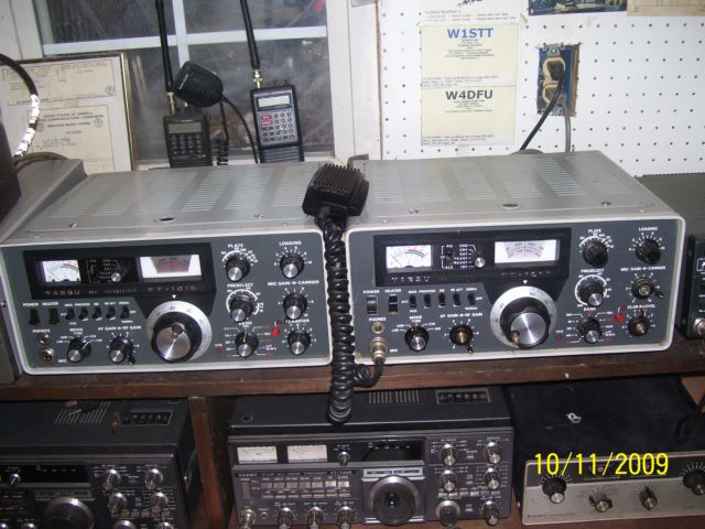
    At 11:30 he rolled in and started to show me all the stuff he found. After that he pulled out two Yaesu Ft-101's. An E and F. He said these are for you. They do not work but maybe you can make a good one. All he said then was Merry Christmas and he had some equipment he wanted me to service. No Problem.

    After looking the units over the F was took apart. Some internal boards and all the knobs and VFO. The E had the RF compartment disassembled. Looks like they were going to use the F for parts. I spent the evening putting both back together. The F is missing three knobs. I put it on the bench first and in a matter of a few minutes had it receiving great. Power output is about 1 watt.

    The E comes on put no RX or TX. So I will have to go through it completely.
    Rigs came with two power cords and a set of spare tubes. Also the user and service manual.

    I think it was a great find and worth the effort to restore. Now got to find that paint code.
    Already downloaded all the stuff from the Fox Tango site.

    Hopefuly I will have two working 101's

  2. #2
    Beach Bum KA2PTE's Avatar
    Join Date
    Aug 2020
    Location
    Veryork
    Posts
    63
    Another ham I know is trying to fix an FT101, I think theres no letter at the end just a plain 101. He says :
    "I have a problem with an FT101. It works fine on AM and USB transmit but on LSB it is transmitting +1.3KHz instead of -1.5KHz. The poor radio had been converted for use on 11 meters AM with an AM filter installed along with rewiring. It was done right but the customer wants it put back to original so I put it back and it still won't do LSB right."

    He later informed me LSB and USB work backwards and the 3 mhz crystals are ok and theres 1 grey wire that was disconnected at both ends and he can't figure out where it goes. One end is somewhere around the mode switch the other is somewhere around pin 10-13 on the voltage regulator board connector.


    Any ideas?

  3. #3
    Administrator N8YX's Avatar
    Join Date
    Feb 2007
    Location
    Out in the sticks
    Posts
    26,083
    The grey wire went from the 11M driver circuit bandswitch position to a coil which was connected to ground. If you turned the bandswitch to 11M, RF power from the pre-driver transistor was shunted to ground. It was necessary to remove the wire if you wanted to use the 11M spot for, say, adding 12M.

    Note that the connection and choke may not appear on the schematics for the RF section of the rig. I'd leave it disconnected and add 12M to the rig for your friend.

    As far as the LSB issue is concerned: What do you measure for BFO frequencies when the rig is set to USL, LSB and AM?
    "Everyone wants to be an AM Gangsta until it's time to start doing AM Gangsta shit."

  4. #4
    Beach Bum KA2PTE's Avatar
    Join Date
    Aug 2020
    Location
    Veryork
    Posts
    63
    Thanks, that explains the grey wire. He says the BFO frequencies on AM, LSB and USB are exactly right. 3181.5 for LSB, 3178.5 for USB and 3179.3 AM

  5. #5
    Administrator N8YX's Avatar
    Join Date
    Feb 2007
    Location
    Out in the sticks
    Posts
    26,083
    Next thing I'd do is to take a look at those frequencies when in transmit. Also look at the VFO frequency - does it change in TX while set to LSB?
    "Everyone wants to be an AM Gangsta until it's time to start doing AM Gangsta shit."

  6. #6
    Beach Bum KA2PTE's Avatar
    Join Date
    Aug 2020
    Location
    Veryork
    Posts
    63
    Ok turns out he was I guess testing it incorrectly , he says "it has to be tuned to upper sideband and lower sideband manually"
    and I guess he forgot to do that. Thanks for the help.

Posting Permissions

  • You may not post new threads
  • You may not post replies
  • You may not post attachments
  • You may not edit your posts
  •