Page 1 of 9 123 ... LastLast
Results 1 to 10 of 88

Thread: Hardware Hackin' the oldies

  1. #1
    Administrator N8YX's Avatar
    Join Date
    Feb 2007
    Location
    Out in the sticks
    Posts
    26,085

    Hardware Hackin' the oldies

    Thread to discuss modifications which add or change functionality of classic gear and keep it viable today.

    The Kenwood R820: Getting more coverage.

    I have a few of these things kicking around the shack, and use two in conjunction with a pair of TS820S transceivers. The third sees duty as a general-coverage Ute monitor of sorts, and it no longer covers the ham bands.

    Primarily, there are two ways to extend or change coverage of an R820 - and some of the tricks I'll discuss can be applied to a TS-820S as well...especially the WARC-band mods.

    [highlight:18ejtptw]Method 1 - re-crystal and add the "Aux" Band components[/highlight:18ejtptw]

    The 820-series PLL/VCO/counter arrangement uses one crystal oscillator/VCO combo per band, and it's easy to swap crystals on the PD board to get different coverage ranges - but you'll need a solder sucker to do it properly. The reference oscillator crystals are on 500KHz multiples and the required frequency for a given band is calculated by:

    Fc = 5.5 + lower band edge

    In this example, we want coverage of 12M, starting at 24.5 MHz. Thus, 5.5 + 24.5 = 30.0000 MHz.

    The crystals used are HC-18/U or HC-49/U (wire lead), 20-30pF series capacitance. (eBay's yer buddy in some cases. I bought an entire bag of the rocks required for 12M for ~$3 and will pass along the savings to anyone who wishes to mod their 820 line. Contrast this to $20 per crystal from ICM!)

    I changed most of the band crystals in my "Ute" '820 and will have the following bandswitched coverage when done:

    2.0-2.5 MHz
    3.0-3.5 MHz
    6.5-7.0 MHz
    13.5-14.0 MHz
    15.5-16.0 MHz (old WWV spot)
    21.5-22.0 MHz
    26.5-28.0 (in three bands)
    29.5-30.0 MHz (left stock...more on this in a bit)
    25.5-26.0 MHz - added to the "Aux" spot

    This gets me the 120M, 90M, 41M, 22M, upper end of the 19M, 13M and 11M SW broadcast bands...as well as the area directly above and below the Class D CB Radio service. It's useful to be able to find who's tearing up 10M on occasion...

    Adding a band to the "Aux" spot requires adding a crystal, a 3.3K resistor, 5.6K resistor and a 150pF ceramic disc capacitor to the PD board. You need to add a 9/32" tunable coil of the correct inductance to the "T11" spot on the VCO board, along with four (or five, depending on band) pF-range ceramic disc capacitors. You must remove the Coil Pack board and add an ANT and two MIX slug-tunable coils, the value of each depending on the new band added.

    Word of Advice: Acquire a junked TS820S and salvage the needed ANT coil from its Coil Pack board, and required the VCO coil from the VCO board. You can also get the two 9/32" MIX coils from this board...but you're going to have to rewind them. I used a total of 8 turns on each of the new coils for the 25.5 MHz band; this should resonate 12M with ease. On a previously converted '820 I would ALL the coils from scratch. A dip meter is invaluable here. It was still a PITA.

    Follow the service manual procedure for adjusting the VCO and Coil Pack coils.

    Your TS-820S can be similarly modified. QST (February 1983) carried a detailed article; much of which I've described here is loosely related.

    [highlight:18ejtptw]Method 2: Electrickery with the Converter unit[/highlight:18ejtptw]

    Kenwood did a neat trick with this receiver: They built a SWBC receiving converter which outputs to 10M and which is capable of preloading the counter, thus giving accurate readout of anything covered by the converter. We're going to take advantage of their design logic to get some extra coverage in a relatively easy fashion.

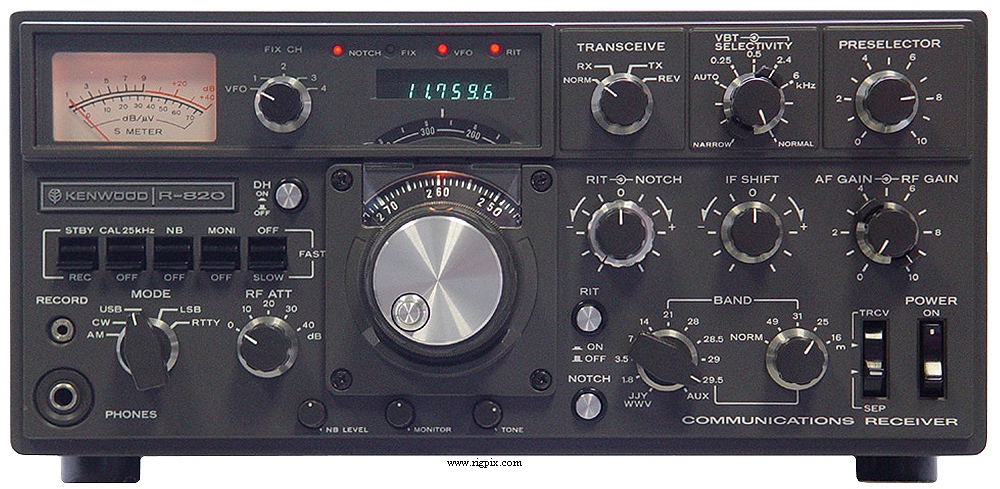
    See the secondary "Band" knob in the picture below? Kenwood tied its activation line to just the 29.5 MHz bandswitch position, but it'll work on the other 10M spots.


    Arm yourself with a service manual, schematics and a soldering iron...and a few 1N4148 diodes. That's all this mod requires.

    First, remove both top and bottom covers and locate the main bandswitch. Look for a WHT/BRN wire which runs from the 29.5 MHz contact to the top rear contact on the SWBC bandswitch. (It's at the anode end of a 1S1555 diode which is connected to two of the wafers.) Unsolder the WHT/BRN wire at the anode end of the diode then solder it to the anode of one of the 1N4148 diodes you sourced for this project. Solder the cathode end of your new diode/wire arrangement to the anode of the 1S1555. Use heat shrink tubing on the diode and wire.

    Now locate the 29.0 MHz (WHT) and 28.5 MHz (GRY) bandswitch wires. Peel a little insulation back at the midpoint of each and solder the anode of a 1N4148 to each. Now solder the cathodes to the anode of the 1S1555, just like you did above. Again, use heat shrink and a little electrical tape on each of the connections. Check for shorts, then power up the receiver. You're hearing stuff...but...the counter is indicating incorrectly at this point!

    There's a fix for that. Study the service manual and the schematic of the PD/VCO board. Then look at what Kenwood did for the 28, 28.5 and 29 MHz bands that they didn't do for the 29.5 MHz band.

    That's right, diodes. These are used to preset bandpass select line "B4" of the counter but aren't needed if voltage is present as a function of the secondary band-select circuit.

    Remove the PD/VCO assembly, invert it and remove the 5 sheet metal screws that secure the cover. Now locate D21 and D22, near the "B1-B4" posts. Snip their anode ends and mode them out of the way, then replace the VCO cover and reinstall the module, connecting the PLL1-PLL5 connectors as you go. Check your work...fire the set up and look smug. It's now displaying properly.

    Each of the four "SWBC" bands employs a tuned bandpass filter, and these must be retuned to allow broader coverage of the "expanded" ranges. I find it best to stagger-tune them with the aid of a sweep generator but you can do it manually if necessary. Just peak on atmospheric noise or signal at several places throughout the whole 1.5 MHz range. (Refer to the R820 service manual for details on the procedure and component identification.)

    [highlight:18ejtptw]Method 3: A little of both[/highlight:18ejtptw]

    The converter's crystals can also be changed to move the coverage around a bit. I would try to stay within 1.5 MHz of either side of "stock", which is as follows:

    5.9-6.4 MHz
    9.4-9.9 MHz
    11.5-12.0 MHz
    17.7-18.2 MHz

    (Yes, it'll cover 17M "out of the box". I took advantage of this and modified my TS-820S to cover 17M, and in doing so I specified the new PD oscillator crystal frequency such that it allows accurate tracking of the R-820's tuning range...thus enabling true 'twins' operation on the 18 MHz band.)

    The crystals required to modify the converter board are HC-18/U or HC-49/U; 20-30pF series capacitance...and their frequency is calculated accordingly:

    29.5 - lower band edge

    Thus, for coverage of 7.0-7.5 MHz (at the old "49M") spot, you'll need a 22.0000 MHz crystal. Again, an easy eBay find.

    Lastly -

    One can modify the WWV/JJY band position of either the R-820 or the TS-820S for 10.0-10.5 MHz operation, thus covering 30M. The February '83 QST article goes into detail about this modification; I'm going to do it to my second "pair" of twins and add 12M to each in the process.

    Should anyone find this writeup useful and want pictures and/or help, I'll be glad to assist.
    "Everyone wants to be an AM Gangsta until it's time to start doing AM Gangsta shit."

  2. #2
    "Island Bartender" KG4CGC's Avatar
    Join Date
    Mar 2007
    Location
    EM84ru, Easley SC
    Posts
    51,301

    Re: Hardware Hackin' the oldies

    Fine business.

  3. #3
    Administrator N8YX's Avatar
    Join Date
    Feb 2007
    Location
    Out in the sticks
    Posts
    26,085

    Re: Hardware Hackin' the oldies

    Quote Originally Posted by KG4CGC
    Fine business.
    I just got parts in the mail to convert both of my FT-901's RF boards to a DBM (instead of a dual MOSFET) arrangement. Likewise its speech processor board, though I am still awaiting band crystals for the sets. Gonna WARC 'em...
    "Everyone wants to be an AM Gangsta until it's time to start doing AM Gangsta shit."

  4. #4
    Administrator N8YX's Avatar
    Join Date
    Feb 2007
    Location
    Out in the sticks
    Posts
    26,085

    Re: Hardware Hackin' the oldies

    More '820 nooz:

    Some of the crystals I needed arrived yesterday. Changing them was easy. Getting the display to read the correct frequency for the new 10 MHz band was another matter entirely, though the actual modification was simple once the circuit was understood.

    Refer to my original post about the SWBC as used in the R-820. Its 31M band crystal is exchanged for a 19.500 MHz unit, which is actually an OEM value for the 20M band segment. But the counter now reads "0.000.0" instead of "10.000.0".

    The fix is as follows:

    Note the blue wire on the lower rear portion of the SWBC band switch; this with the receiver upside down and the front oriented towards you. There is a wire jumper which connects the bandswitch terminal with the blue wire to the next terminal to its right. Desolder the blue wire, then move it one terminal to the left (white and purple wire). Solder it there. Next, run a jumper from the terminal where the blue wire was to the terminal with the brown wire, immediately to its right.

    Check your work and power the receiver. It should indicate "10.000.0" to "10.500.0" throughout the tuning range, but if you dip below 10.000 it'll read "19.999.9", etc. There isn't a cure for this, as we've hard-wire-selected the next highest counter prescalar. (Incidentally, as delivered from Kenwood the high end of the 29.5 MHz segment reads "20.000.0" when you tune past 29.999.9...on ALL '820-series equipment. This is what you get with a counter of a scalar/bandpass design.)

    Re-peak the band-pass filter coils on the converter board as shown in the service manual. The '820 I converted has good sensitivity but I'm seeing a pair of images...one at 10.130 and another at 10.115. When I find the offenders I'm going to construct a series-tuned trap and place it across the output of the 31M bandpass filter to ground.

    Speaking of bandpass filters...if you really get carried away with shifting the converter crystal frequencies (like I did), odds are you're going to have to change some capacitor values in order to get the coils to tune properly. The 49M spot on mine now covers 7.5-8.0 MHz and I'm going to swap the existing caps for a bunch with slightly lower values. Either that...or pony up $40 for two more crystals, one at 13.000 MHz (to allow the 40M spot to cover 7.5-8.0) and 23.000 MHz (to allow the converter to cover 6.5-7.0, which is very close to its designed range).

    As with anything, there's always backlash. Mine came in the form of a worn gear drive on the VFO. I spent the better part of last evening and until around noon today rebuilding the mechanical portion of things to ensure a smooth, lash-free drive.

    If you're a fan of the Kenwood or Yaesu hybrids, I'll give some advice:

    1) Mechanical components wear, faster without lube;
    2) If your rig's VFO sits pretty much in one spot its whole life, this may not be a problem;
    3) If the rig was heavily used and not cared for, wear certainly will be an issue at some point.

    In the '820's VFO assembly, an idler gear set is used to reduce the rotational motion between the tuning shaft and the VFO capacitor rotor shaft. Each end of the idler gear shaft is held captive in one of two brass plates which comprise the support assemblies for the drive unit. If the hole becomes elongated or wears oversize, the resulting slack (albeit small) is enough to thoroughly muck up the tuning...to the point that getting an SSB signal "dead on" is extremely difficult.

    My solution is to buy up these parts as I find them (cheap!) and cannibalize as necessary. Of course, I plan on keeping my hybrids around for a while.

    The R-820's 20M band spot now tunes from 13.5 to 14.0. I'll see if I can hear any HiFer beacons (including Kelli's) around 13.555 with the rig...
    "Everyone wants to be an AM Gangsta until it's time to start doing AM Gangsta shit."

  5. #5
    Master Navigator n4aud's Avatar
    Join Date
    Jul 2007
    Location
    Wise, VA
    Posts
    1,577

    Re: Hardware Hackin' the oldies

    Where are you getting your crystals?
    I'd like to have a couple of fixed channels on my TS-520 on frequencies where I participate in nets.

  6. #6
    Administrator N8YX's Avatar
    Join Date
    Feb 2007
    Location
    Out in the sticks
    Posts
    26,085

    Re: Hardware Hackin' the oldies

    Quote Originally Posted by n4aud
    Where are you getting your crystals?
    I'd like to have a couple of fixed channels on my TS-520 on frequencies where I participate in nets.
    For the custom-made rocks: ICM, primarily. I've also found them at a number of places online, both new and surplus.

    Let me know the frequencies you need. Ye Olde Junque-Box may yield a surprise or two.
    "Everyone wants to be an AM Gangsta until it's time to start doing AM Gangsta shit."

  7. #7
    Administrator N8YX's Avatar
    Join Date
    Feb 2007
    Location
    Out in the sticks
    Posts
    26,085

    Re: Hardware Hackin' the oldies

    I'm sitting here in the shack/computer lab enjoying the fruits of my labors vis the eBay "rescue" R-820. Seller stated it was blown up, fried, kaput, missing parts, etc...

    The only missing part I'm aware of at this time is the shield which covers the IF-A (filter) board, and I've laid out a piece of double-sided copper-clad board with the shapes necessary to construct another. That's probably easier than making one from sheet metal and the results will be the same.

    The VFO backlash problem was solved by preloading each half of the split gear assemblies by one tooth as the drives were being put together. That, and a careful selection of end plates married to reduction drives resulted in a smooth-tuning unit in the radio and two more "spare" VFOs, ready to go if necessary. No slop; no backlash.

    Total investment in the rig was $227 + $20 for a spare counter board + $10 for some hardware...and maybe $140 on extra band crystals. I still may purchase a couple more and some filters for the rig. For those unfamiliar with the receiver, it was the first Kenwood radio to introduce Variable-Bandwidth Tuning, and it works well. But not as good as a nice, sharp-skirted filter. Since this rig is primarily used outside the ham bands, I'm thinking about adding a 1.8 KHz B/W SSB filter...a 6 KHz AM filter...and either a 4 KHz AM filter (for synchronous AM detection) or a 500hz CW filter (for 425-shift RTTY). Of course, the rig's IF Shift is inactive while in AM mode...thus necessitating yet another mod if I'm to use it for SAM detection. Likewise, the filter board's switching logic will need a bit of re-engineering in order to be able to select the correct filter based on mode.

    Next up in the '820 mod series is adding 30 and 12M WARC to a TS-820S/R-820 pair. The Yahoo Group "Kenwood Hybrids" which I'm a member of has at least one other gent who's modding his '820, and I'm thinking about sending a link to this thread to the membership at large.
    "Everyone wants to be an AM Gangsta until it's time to start doing AM Gangsta shit."

  8. #8
    Master Navigator n4aud's Avatar
    Join Date
    Jul 2007
    Location
    Wise, VA
    Posts
    1,577

    Re: Hardware Hackin' the oldies

    Quote Originally Posted by N8YX
    Quote Originally Posted by n4aud
    Where are you getting your crystals?
    I'd like to have a couple of fixed channels on my TS-520 on frequencies where I participate in nets.
    For the custom-made rocks: ICM, primarily. I've also found them at a number of places online, both new and surplus.

    Let me know the frequencies you need. Ye Olde Junque-Box may yield a surprise or two.
    I participate in a couple of nets on 3947 khz. Kenwood says that requires a 5054.5 crystal.

  9. #9
    Administrator N8YX's Avatar
    Join Date
    Feb 2007
    Location
    Out in the sticks
    Posts
    26,085

    Re: Hardware Hackin' the oldies

    Quote Originally Posted by n4aud
    I participate in a couple of nets on 3947 khz. Kenwood says that requires a 5054.5 crystal.
    Just checked two online sources which list a bunch of surplus rocks - no dice.

    Will check my stash and let you know what I come up with.
    "Everyone wants to be an AM Gangsta until it's time to start doing AM Gangsta shit."

  10. #10
    Master Navigator n4aud's Avatar
    Join Date
    Jul 2007
    Location
    Wise, VA
    Posts
    1,577

    Re: Hardware Hackin' the oldies

    Thanks.

Posting Permissions

  • You may not post new threads
  • You may not post replies
  • You may not post attachments
  • You may not edit your posts
  •