Page 1 of 2 12 LastLast
Results 1 to 10 of 17

Thread: Amplifier Rework Project

  1. #1
    Master Navigator koØm's Avatar
    Join Date
    Mar 2009
    Location
    Queensgate
    Posts
    2,220

    Amplifier Rework Project

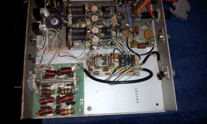
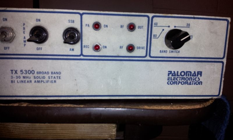
    I have an amplifier that was constructed by the real "Palomar Labs" back in the 70's, it is a Model #5300 with a low pass filter section on the output and, a band switch selecting the 80 through 10 meter low pass filters. It has a regulated B class bias voltage on the input transformer, the power switch now activates a relay to switch +12 volts to the amp and, the Antenna Switch relay failed and had to be replaced with a different model because the stock part is no longer attainable (and was too small for the output).


    I also have an Input matching circuit board designed to match a 50 ohm transmitter to the cathode of a four sweep tube amplifier


    So, i'm thinking that I can hook the original 50 impedance side to the input transformer and the output side to the MFJ 259 antenna analyzer and rework the caps and coils to work from 50 ohm radio input to transistor input matching impedance.

    Does this sound like a feasible project?


    BTW: also posted in Technical section of the swamp; I know i'm gonna get a bunch of Snarky-Chicken Band remarks but, I really thinking about doing this.

    .


  2. #2
    Administrator N8YX's Avatar
    Join Date
    Feb 2007
    Location
    Out in the sticks
    Posts
    26,083
    First thing to look at is biasing, and how the design regulates it. Thermal stability is important here.
    "Everyone wants to be an AM Gangsta until it's time to start doing AM Gangsta shit."

  3. #3
    Master Navigator koØm's Avatar
    Join Date
    Mar 2009
    Location
    Queensgate
    Posts
    2,220
    Quote Originally Posted by N8YX View Post
    First thing to look at is biasing, and how the design regulates it. Thermal stability is important here.
    bias.jpg

    The 3055 / regulator is bolted to heat sink

    .


  4. #4
    Orca Whisperer PA5COR's Avatar
    Join Date
    Feb 2009
    Location
    The Netherlands
    Posts
    12,186
    Do the transistors all have been selected for the same bias setting? Motorola has a color dot for that, even then I build my amps with a bias circuit for each transistor with heat tracking as well.
    "If the Republicans will stop telling lies about the Democrats, we will stop
    telling the truth about them." - Adlai Stevenson (1900-1965)
    “I’m not liberal/conservative, I’m anti-idiotarian.”
    At some point in the last 20 years, the left moved to the center, and the right moved into a mental institution

  5. #5
    Master Navigator koØm's Avatar
    Join Date
    Mar 2009
    Location
    Queensgate
    Posts
    2,220
    Quote Originally Posted by PA5COR View Post
    Do the transistors all have been selected for the same bias setting? Motorola has a color dot for that, even then I build my amps with a bias circuit for each transistor with heat tracking as well.
    Nope, both pair of input transformers share the same bias supply.

    5300.jpg


  6. #6
    Orca Whisperer PA5COR's Avatar
    Join Date
    Feb 2009
    Location
    The Netherlands
    Posts
    12,186
    I see, and no temperature control either per transistor, which can cause a thermal run away when one is not in the selected bias configuration.
    Each of my transistors had a thermally coupled diode over the transistors each with it's own regulated bias from a low impedance source.
    Might be overkill, but according the Motorola handbook Engineering Bulletins that was how they did it and I followed their design.
    Transistors were quite expensive then.... ;)
    The rest looks like the same AB Motorola design, wideband input and output coupling and transformers.
    Even used it ( adapted) for 2 meter with 2 x the MRF 247 transistors.
    That one didn't have much gain, 35 watts in for 160 out but that was satisfactory then.
    Running that in 2 x 12 element beams was a hoot ;)

    Look on the net for the schematic diagram of the HLA 300V amplifier from European make, there is a HAM version of it with band filtering etc reasonably clean too for 300 watt.
    RM Italy does make a HLA-300V, 450 watt amplifier that has full auto band switch low pass filtering, with power meter and remote keying. I have tested the amplifier and it passes FCC certification but has not been certificated as of yet. You can buy them for about $360.
    You do need a 50 to 60 amp power supply for it though...

    http://pa0fri.home.xs4all.nl/Lineair.../schematic.pdf
    Schematic diagram.

    http://pa0fri.home.xs4all.nl/Lineair.../hla300eng.htm

    Detailed description of that amplifier and test.
    Last edited by PA5COR; 10-24-2014 at 02:24 PM.
    "If the Republicans will stop telling lies about the Democrats, we will stop
    telling the truth about them." - Adlai Stevenson (1900-1965)
    “I’m not liberal/conservative, I’m anti-idiotarian.”
    At some point in the last 20 years, the left moved to the center, and the right moved into a mental institution

  7. #7
    Administrator N8YX's Avatar
    Join Date
    Feb 2007
    Location
    Out in the sticks
    Posts
    26,083
    Cor nailed it - per-device thermal feedback to regulate bias or you'll get one or two that "hog" the load as die temps increase.

    That bias circuit should be your first remediation point.
    "Everyone wants to be an AM Gangsta until it's time to start doing AM Gangsta shit."

  8. #8
    Orca Whisperer PA5COR's Avatar
    Join Date
    Feb 2009
    Location
    The Netherlands
    Posts
    12,186
    https://forums.hamisland.net/showthr...04-amp-project

    Nice work here with a balderdash of info about such amp ;)
    "If the Republicans will stop telling lies about the Democrats, we will stop
    telling the truth about them." - Adlai Stevenson (1900-1965)
    “I’m not liberal/conservative, I’m anti-idiotarian.”
    At some point in the last 20 years, the left moved to the center, and the right moved into a mental institution

  9. #9
    Master Navigator koØm's Avatar
    Join Date
    Mar 2009
    Location
    Queensgate
    Posts
    2,220
    Quote Originally Posted by PA5COR View Post
    https://forums.hamisland.net/showthr...04-amp-project

    Nice work here with a balderdash of info about such amp ;)
    I remember that thread, he documented his whole project but, there are a couple of major differences:
    1. He started with a bare board, that was new construction; my circumstance is repair / retuning
    2. His amp used control modules that are 40 years forward that the one I am working with.
    3. His amp is designed to Fixed station use, mine is +12 vdc mobile
    4. His design uses high input impedance devices that do not require toroid transformers thus allowing for dedicated bias controls for each transistor.


    I digested the circuit at http://www.ab4oj.com/dl/eb104.pdf along with the write up on the operation of the amp. I found it interesting that the boiler-plate design of the now commonly accepted EB104 based amplifer has bias voltage ran through a chip that controlled voltage level and current load but, the bias voltages for each device was paralleled from a single output. The final voltage adjustments for the individual devices were from a voltage dividers behind the regulator chip; higher tech voltage control but, same circuit that was used in the 1980's device.

    After some thought, looking at the Palomar TX-5300 circuit, I figured one way to install individual bias systems would be to
    1. Connect the base of the transistor to the impedance matching transformer via large .001 uf capacitors
    2. Isolate the impedance matching transformer from ground,
    3. Apply bias voltage through chokes to each base, behind the now DC blocking capacitor in the base circuit.
    4. I will leave the temperature compensation (wire a thermistor in) circuit for thermal tracking up to you guys to figure out.


    Just some thoughts.

    BTW: The .001 capacitors which are paralleled with the 15 ohms resistors in the base circuit is in error, they are not in the amplifier that I have; if they were there, RF drive would be divided / bypassed to ground.
    .
    Last edited by koØm; 10-26-2014 at 03:53 PM.


  10. #10
    La Rata Del Desierto K7SGJ's Avatar
    Join Date
    Feb 2010
    Location
    The Desert
    Posts
    16,791
    Don't forget to ground the B+
    A clear conscience is usually a sign of a bad memory

    RIP ALBI-W3MIV RIP RUSS-W5RB RIP BOB-VK3ZL


Posting Permissions

  • You may not post new threads
  • You may not post replies
  • You may not post attachments
  • You may not edit your posts
  •